Microwave imaging
Microwave imaging is a science which has been evolved from older detecting/locating techniques (e.g., radar) in order to evaluate hidden or embedded objects in a structure (or media) using electromagnetic (EM) waves in microwave regime (i.e., ~300 MHz-300 GHz).[1] Engineering and application oriented microwave imaging for non-destructive testing is called microwave testing, see below.
Microwave imaging techniques can be classified as either quantitative or qualitative. Quantitative imaging techniques (are also known as inverse scattering methods) give the electrical (i.e., electrical and magnetic property distribution) and geometrical parameters (i.e., shape, size and location) of an imaged object by solving a nonlinear inverse problem. The nonlinear inverse problem is converted into a linear inverse problem (i.e., Ax=b where A and b are known and x (or image) is unknown) by using Born or distorted Born approximations. Despite the fact that direct matrix inversion methods can be invoked to solve the inversion problem, this will be so costly when the size of the problem is so big (i.e., when A is a very dense and big matrix). To overcome this problem, direct inversion is replaced with iterative solvers. Techniques in this class are called forward iterative methods which are usually time consuming. On the other hand, qualitative microwave imaging methods calculate a qualitative profile (which is called as reflectivity function or qualitative image) to represent the hidden object. These techniques use approximations to simplify the imaging problem and then they use back-propagation (also called time reversal, phase compensation, or back-migration) to reconstruct the unknown image profile. Synthetic aperture radar (SAR), ground-penetrating radar (GPR), and frequency-wave number migration algorithm are some of the most popular qualitative microwave imaging methods[1].
Principles
[edit]In general, a microwave imaging system is made up of hardware and software components. The hardware collects data from the sample under test. A transmitting antenna sends EM waves towards the sample under test (e.g., human body for medical imaging). If the sample is made of only homogeneous material and is of infinite size, theoretically no EM wave will be reflected. Introduction of any anomaly which has different properties (i.e., electrical/magnetic) in comparison with the surrounding homogeneous medium may reflect a portion of the EM wave. The bigger the difference between the properties of the anomaly and the surrounding medium is, the stronger the reflected wave will be. This reflection is collected by the same antenna in a monostatic system, or a different receiver antenna in bistatic configurations.

To increase the cross-range resolution of the imaging system, several antennas should be distributed over an area (which is called the sampling area) with a spacing less than the operating wavelength. However, the mutual coupling between the antennas, which are placed close to each other, may degrade the accuracy of the collected signals. Moreover, the transmitter and receiver system will become very complex. To address these problems, one single scanning antenna is used instead of several antennas. In this configuration, the antenna scans over the entire sampling area, and the collected data is mapped together with their antenna position coordinates. In fact, a synthetic (virtual) aperture is produced by moving the antenna (similar to the synthetic aperture radar principle[2]). Later, the collected data, which is sometimes referred to as raw data, is fed into the software for processing. Depending on the applied processing algorithm, microwave imaging techniques can be categorized as quantitative and qualitative.
Applications
[edit]Microwave imaging has been used in a variety of applications such as: nondestructive testing and evaluation (NDT&E, see below), medical imaging, concealed weapon detection at security check points, structural health monitoring, and through-the-wall imaging.
Microwave imaging for medical applications is also becoming of more interest. The dielectric properties of malignant tissue change significantly in comparison with the properties of normal tissue (e.g., breast tissue). This difference translates into a contrast which can be detected by microwave imaging methods. As one example, there are several research groups all around the world working on developing efficient microwave imaging techniques for early detection of breast cancer.[3]

Ageing of infrastructure is becoming a serious problem worldwide. For example, in reinforced concrete structures, corrosion of their steel reinforcements is the main cause of their deterioration. In U.S. alone, repair and maintenance cost due to such corrosion is about $276 billion per year,[4] [3].
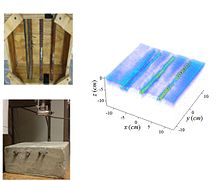
Recently, microwave imaging has shown great potential to be used for structural health monitoring. Lower frequency microwaves (e.g., <10 GHz) can easily penetrate through concrete and reach objects of interest such as reinforcement bars (rebars). If there is any rust on the rebar, since rust reflects less EM waves in comparison with sound metal, the microwave imaging method can distinguish between rebars with and without rust (or corrosion).[citation needed] Microwave imaging also can be used to detect any embedded anomaly inside concrete (e.g., crack or air void).
These applications of microwave imaging are part of non-destructive (NDT) testing in civil engineering. More on microwave imaging in NDT is described in the following.
Microwave testing
[edit]Microwave testing uses the scientific basics of microwave imaging for the inspection of technical parts with harmless microwaves. Microwave testing is one of the methods of non-destructive testing (NDT). It is restricted to tests of dielectric, i. e. non-conducting material. This includes glass-fibre reinforced plastic (GRP, GFRP).[5] Microwave testing can be used to inspect components also in a built-in state, e. g. built-in non-visible gaskets in plastic valves.

Principle
[edit]
The microwave frequencies extend from 300 MHz to 300 GHz corresponding to wavelengths between 1 m and 1 mm. The section from 30 GHz to 300 GHz with wavelengths between 10 mm and 1 mm is also called millimeter waves. Microwaves are in the order of the size of the components to be tested. In different dielectric media they propagate differently fast and at surfaces between them they are reflected. Another part propagates beyond the surface. The larger the difference in the wave impedance, the larger is the reflected part.
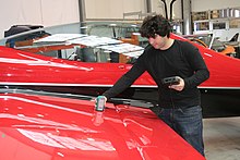
In order to find material defects, a test probe, attached or in a small distance, is moved over the surface of the device under test. This can be done manually or automatically.[6] The test probe transmits and receives microwaves.
Changes of the dielectric properties at surfaces (e. g. shrinkage cavities, pores, foreign material inclusion, or cracks) within the interior of the device under test reflect the incident microwave and send a part of it back to the test probe, which acts as a transmitter and as a receiver.[7][8]
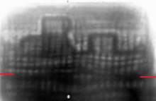
The electronic data evaluation leads to a display of the results, e. g. as a B-scan (cross sectional view) or as a C-scan (top view). These display methods are adopted from ultrasonic testing.

Procedures
[edit]Besides the reflection method also the through transmission method is possible, in which separate transmit and receive antennas are used. The backside of the device under test (DUT) must be accessible and the method gives no information about the depth of a defect within the DUT.
Microwave tests are possible with constant frequency (CW) or with continuously tuned frequency (FMCW). FMCW is advantageous to determine the depth of defects within the DUT.
A test probe attached to the DUT's surface gives information about the material distribution below the point of contact. When moving over the DUT surface point by point many such information is stored and then evaluated to give an overall image. This takes time. Directly imaging procedures are faster: Microwave versions are either electronic[9] or make use of planar microwave detector consisting of a microwave absorbing foil and an infrared camera (NIDIT procedure[10]).

Applications
[edit]Microwave testing is a useful NDT method for dielectric materials. Among them are plastics, glass-fiber reinforced plastics (GFRP), plastic foams, wood, wood-plastic composites (WPC), and most types of ceramics. Defects interior in the DUT and at its surface can be detected, e. g. in semi-finished products or pipes.
Special applications of microwave testing are non-destructive
- moisture measurements
- wall thickness measurements
- measurements of paint thickness on carbon composites (CFRP)
- condition monitoring, e. g. presence of gaskets in assembled valves, rubber based piping in heat exchangers[11]
- measurement of material parameters, e.g. permittivity and residual stress
- disbond detection in strengthened concrete bridge members retrofitted with carbon fiber reinforced (CFRP) composite laminates[12]
- corrosion and precursor pitting detection in painted aluminum and steel substrates[12]
- flaw detection in spray-on foam insulation and the acreage heat tiles of the Space Shuttle.[12]
Microwave testing is used in many industrial sectors:
- aerospace, e. g. non-destructive paint thickness measurements on CFRP[13]
- automobile, e. g. NDT of organo sheet components and of GFRP leaf springs[14]
- civil engineering, e. g. radar applications[15]
- energy supply, e. g. test of rotor blades of wind power plants, riser pipe[16]
- security, e. g. body scanner on airports[9]
In the last years the need for NDT has increased generally and especially also for dielectric materials. For this reason and because microwave technics more and more are used in consumer products and hereby became much less expensive, NDT with microwaves increases. In recognizing this growing importance, in 2011 the Expert committee for microwave and THz procedures[17] of the German Society of Non-Destructive Testing (DGZfP) was founded as in 2014 the Microwave Testing Committee of the American Society for Non-Destructive Testing (ASNT). Standardization work is at the beginning.
References
[edit]- ^ "Synthetic aperture radar-based techniques and reconfigurable antenna design for microwave imaging of layered structures". Retrieved 2014-05-07.
- ^ M. Soumekh, Synthetic Aperture Radar Signal Processing, 1st ed. New York, NY, USA: Wiley, 1999.
- ^ Bond E J, Li X, Hagness S C and Van Veen B D 2003 Microwave imaging via space-time beamforming for early detection of breast cancer IEEE Trans. Antennas Propagat. 51 1690-705
- ^ G. Roqueta, L. Jofre, and M. Feng, “Microwave Non-Destructive evaluation of corrosion in reinforced concrete structures,” in Proc. 5th Eur. Conf.Antennas Propagation (EUCAP),Apr. 11–15, 2011, pp. 787–791.
- ^ Li, Zhen (29 Apr 2019). "A review of microwave testing of glass fibre-reinforced polymer composites". Nondestructive Testing and Evaluation. 34 (4): 429–458.
- ^ "Application note from MVG/Satimo. 2 September 2017".
- ^ Balasubramanian, Vishal; Niksan, Omid; Jain, Mandeep C.; Golovin, Kevin; Zarifi, Mohammad H. (2023-08-15). "Non-destructive erosive wear monitoring of multi-layer coatings using AI-enabled differential split ring resonator based system". Nature Communications. 14 (1): 4916. doi:10.1038/s41467-023-40636-9. ISSN 2041-1723.
- ^ Balasubramanian, Vishal; Jain, Mandeep C.; Golovin, Kevin; Zarifi, Mohammad H. (2023-01-06). "Real-time Non-Destructive Erosion Monitoring of Coatings using Passive Microwave Split Ring Resonator Sensor". IEEE: 01–04. doi:10.1109/ICCE56470.2023.10043427. ISBN 978-1-6654-9130-3.
{{cite journal}}: Cite journal requires|journal=(help) - ^ a b "Security through technology Information of ROHDE & SCHWARZ GmbH & Co. KG. 2 September 2017" (PDF).
- ^ "Microwave Testing: an Overview. Application note of FIT-M. 2 September 2017" (PDF).
- ^ "Rubber-based heat exchanger inlet and outlet piping Application note from Evisive. 2 September 2017" (PDF).
- ^ a b c S. Kharkovsky and R. Zoughi, “Microwave and millimeter wave nondestructive testing and evaluation—Overview and recent advances,” IEEE Instrum. Meas. Mag., vol. 10, pp. 26–38, Apr. 2007.
- ^ "Video about paint thickness measurement on CFRP - Application note of FIT-M. 2 September 2017".
- ^ "Microwave testing of GFRP leaf springs - Application note from FIT-M. 2 September 2017" (PDF).
- ^ "Christiane Maierhofer: Radaranwendungen im Bauwesen. In: ZfP-Zeitung 72, Dezember 2000, 43-50 www.ndt.net. 2 September 2017" (PDF).
- ^ "Scanning Report of Flexible Riser Pipe Section - Application note from Evisive. 2 September 2017" (PDF).
- ^ "Expert Committee MTHz of the DGZfP - 2 September 2017".
Literature
[edit]- Joseph T. Case, Shant Kenderian: MWNDT – An Inspection Method. In: Materials Evaluation, March 2017, 339-346. (This paper contains many links regarding microwave testing)
- Reza Zoughi: Microwave Non-Destructive Testing and Evaluation Kluwer Academic Publishers, Dordrecht 2000.
- N. Ida: Microwave NDT Springer Science & Business Media, Luxembourg, 2012
