AT (form factor)
This article includes a list of general references, but it lacks sufficient corresponding inline citations. (April 2009) |

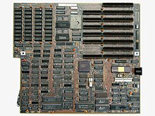
In the era of IBM compatible personal computers, the AT form factor comprises the dimensions and layout (form factor) of the motherboard for the IBM AT. Baby AT motherboards are slightly smaller, measuring 8.5" by 13".[1] Like the IBM PC and IBM XT models before it, many third-party manufacturers produced motherboards compatible with the IBM AT form factor, allowing end users to upgrade their computers for faster processors. The IBM AT became a widely copied design in the booming home computer market of the 1980s. IBM clones made at the time began using AT compatible designs, contributing to its popularity. In the 1990s many computers still used AT and its variants. Since 1997, the AT form factor has been largely supplanted by ATX.
Design
[edit]
The original AT motherboard, later known as "Full AT", is 13.8 × 12 inches (351 × 305 mm), which means it will not fit in "mini desktop" or "minitower cases". The board's size also means that it takes up space behind the drive bays, making installation of new drives more difficult. (In IBM's original heavy-gauge steel case, the two 5+1⁄4" full-height drive bays overhang the front of the motherboard. More precisely, the left bay overhangs the motherboard, while the right bay is subdivided into two half-height bays and additionally extends downward toward the bottom of the chassis, allowing a second full-height fixed disk to be installed below a single half-height drive.)
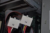
The power connectors for AT motherboards are two nearly identical 6-pin plugs and sockets. As designed by IBM, the connectors are mechanically keyed so that each can only be inserted in its correct position, but some clone manufacturers cut costs and used unkeyed (interchangeable) connectors. Unfortunately, the two power connectors it requires are not easily distinguishable, leading many people to damage their boards when they were improperly connected; when plugged in, the two black wires on each connector must be adjacent to each other, making a row of four consecutive black wires (out of the total 12). Technicians developed mnemonic devices to help assure proper installation, including "black wires together in the middle" and "red and red and you are dead".
Variants
[edit]

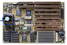
In 1987, the Baby AT form factor was introduced, based on the motherboard found in the IBM PC/XT 286 (5162)[2] and soon after all computer makers abandoned AT for the cheaper and smaller Baby AT form factor, using it for computers that spanned several generations, from those that used 286 processors to the P5 Pentium and a limited number of Pentium II systems. These motherboards have similar mounting hole positions and the same eight card slot locations as those with the AT form factor, but are 8.5 in (216 mm) wide and marginally shorter than full-size AT boards, with a maximum length of 13 in (330 mm). However, Baby AT boards were mostly shorter than this, typically 9 to 10 in (229 to 254 mm).[3] The size and flexibility of this kind of motherboard were the key to success of this format. The development of bigger CPU coolers—and the fact that they blocked full-length PCI and ISA cards—spelled the end of Baby AT and was the main impetus for its successor ATX. While the AT standard is now considered to be mostly obsolete, some industrial computers still use it.
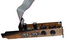
In 1995, Intel introduced ATX, a form factor which gradually replaced older Baby AT motherboards. During the late 1990s, a great majority of boards were either Baby AT or ATX. Many motherboard manufacturers favored Baby AT over ATX as many computer cases and power supplies in the industry were still designed for AT boards and not ATX boards. Also, the lack of an eighth slot on ATX motherboards kept it from being used in some servers. Later Baby AT boards supported both AT and ATX power connectors in addition to ATX features such as standby power (allowing for a low voltage power switch, as well as Wake-on-LAN/Wake-on-Modem Ring[4]) and USB by use of an ATX Form Card. After the industry shifted to ATX motherboard configurations, it became common to design cases and power supplies to support both Baby AT and ATX motherboards.
Power connector
[edit]The connector at the board is two Molex 15-48-0106 connectors. This mates with a Molex 90331.
| Color | Pin | Signal |
|---|---|---|
| Orange | P8.1 | Power good |
| Red | P8.2 | +5 V |
| Yellow | P8.3 | +12 V |
| Blue | P8.4 | −12 V |
| Black | P8.5 | Ground |
| Black | P8.6 | Ground |
| Black | P9.1 | Ground |
| Black | P9.2 | Ground |
| White | P9.3 | −5 V |
| Red | P9.4 | +5 V |
| Red | P9.5 | +5 V |
| Red | P9.6 | +5 V |
References
[edit]- ^ "Baby AT". Retrieved 13 Apr 2021.
- ^ "minuszerodegrees.net". Archived from the original on 2015-03-16.
- ^ "Baby AT motherboard". PC Magazine. PC Mag Digital Group. Retrieved 31 October 2020.
- ^ "35883101 - 883101.pdf" (PDF). PC Partner. 8 Jun 2005. Retrieved 31 Oct 2020.
