
File:Hertz radio wave experiments - refraction.png
No higher resolution available.
Hertz_radio_wave_experiments_-_refraction.png (387 × 201 pixels, file size: 6 KB, MIME type: image/png)
| This is a file from the Wikimedia Commons. Information from its description page there is shown below. Commons is a freely licensed media file repository. You can help. |
Summary
| Description |
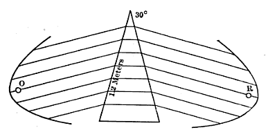
English: Diagram of experiment performed by Heinrich Hertz in 1888 demonstrating refraction of radio waves. At left is Hertz's spark-gap transmitter consisting of a dipole antenna of two brass bars with a spark gap between them, powered by high voltage from a Ruhmkorff coil (not shown) attached to the dipole. High voltage from the coil causes sparks to jump between the halves of the dipole, creating high frequency oscillating currents in the dipole which radiate a pulse of radio waves. At right is Hertz's receiver, consisting of a similar dipole and parabolic reflector attached to a micrometer spark gap. The transmitter and receiver are seen end on; the reflectors were actually 2 m long. The transmitter generated 66 cm radio waves in the UHF band at about 450 MHz. Between the transmitter and receiver Hertz placed a prism of pitch 1.5 m high with an angle of 30°. With the apparatus as shown Hertz found the prism bent the radio waves through an angle of 22°, similarly to the way a glass prism would bend a ray of light. From this angle Hertz calculated that the index of refraction of the pitch for radio waves was 1.69. |
| Date | |
| Source | Retrieved December 17, 2015 from George Washington Pierce (1910) Principles of Wireless Telegraphy, McGraw-Hill Book Co., New York, p. 55, fig. 34 on Google Books |
| Author | George Washington Pierce |
Licensing
This media file is in the public domain in the United States. This applies to U.S. works where the copyright has expired, often because its first publication occurred prior to January 1, 1930, and if not then due to lack of notice or renewal. See this page for further explanation.
|
 | |
 |
File history
Click on a date/time to view the file as it appeared at that time.
| Date/Time | Thumbnail | Dimensions | User | Comment | |
|---|---|---|---|---|---|
| current | 00:50, 18 December 2015 | | 387 × 201 (6 KB) | Chetvorno | User created page with UploadWizard |
File usage
The following page uses this file:
Global file usage
The following other wikis use this file:
- Usage on bn.wiki.x.io
- Usage on mt.wiki.x.io